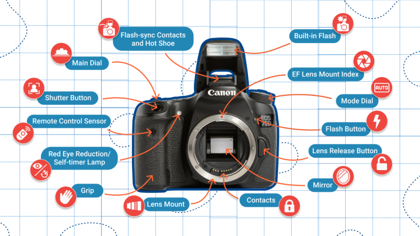
I’m not going to invest a lot of time in this article on the mechanical aspects of digital SLRs.
- Light path. The yellow arrows represent an overly simplified path for the light entering the lens and making its way to the viewfinder and sensor. In reality, the light is refracted at angles as it passes through the lens elements (2), and is redirected down to the autofocus sensor by the mirror (3) or up to the focus screen (4) or through the shutter to the sensor (9).
- Lens components. Lenses include a differing number of elements made from glass, plastic, or another product. These aspects are fixed in place, or can relocate relation to other aspects to focus or zoom the image, or, in an image-stabilized lens, be shifted to compensate for camera movement
- Mirror. The mirror is a flip-up partly silvered part that directs the majority of the light upwards towards the seeing system and exposure meters, and some of the light downwards toward the autofocus elements. (In some SLR-like cams, a non-moving mirror may bounce light upwards to an autofocus system, while permitting the rest of the illumination to pass through to the sensing unit for live watching in an electronic viewfinder to back-panel LCD.).
- Focus screen. When the mirror is turned down, light that has actually travelled through the lens is concentrated on this screen.
Pentaprism/pentamirror. This optical component can be a solid glass block, or pentaprism, silvered on 2 surfaces to show the light, or a less-efficient (in regards to light transmission) hollow structure, a pentamirror, that uses only mirrors. The reflective surfaces reverse the focus screen image gotten from the lens/lower mirror both laterally and vertically, producing a right-reading view.
In the typical DSLR, the direct exposure meter discovers light in the viewingpath, utilizing a range of points in the frame that range in number from a lots to more than 2,000, depending on the electronic camera. Readings might include brightness only, or capture full red/green/blue information to allow the video camera to make direct exposure choices based on a matrix of points, a little “spot meter” set of points, or a center-weighted average of the points translated.
Some viewfinders have a shutter that can be closed to keep light from entering the seeing system and impacting the exposure meter (6 ). Vendors also might provide a rubber or plastic cover to slide over the viewfinder window to obstruct light. Extra devices, such as a magnifier lens or right-angle audience, might be provided for the viewfinder.
Some of the light from the lens is shown downwards to this sensor. It uses pairs of lenses (usually 3 to 51 pairs, depending on the camera) to divide off portions of the beam to form autofocus points or zones that are lined up, in rangefinder style, to allow stage detection autofocus functions.
The shutter is a pair of vertically taking a trip drapes (9, left) that open consecutively to produce a gap for light from the lens to pass through when the main mirror flips up. The sensing unit (9, right) consists of light-sensitive photo sites that tape the image and pass it off to the electronic camera’s analog-to-digital signal processing chip, and then to a memory card for storage.

